Thursday, October 31, 2013

Cooling the Radiator


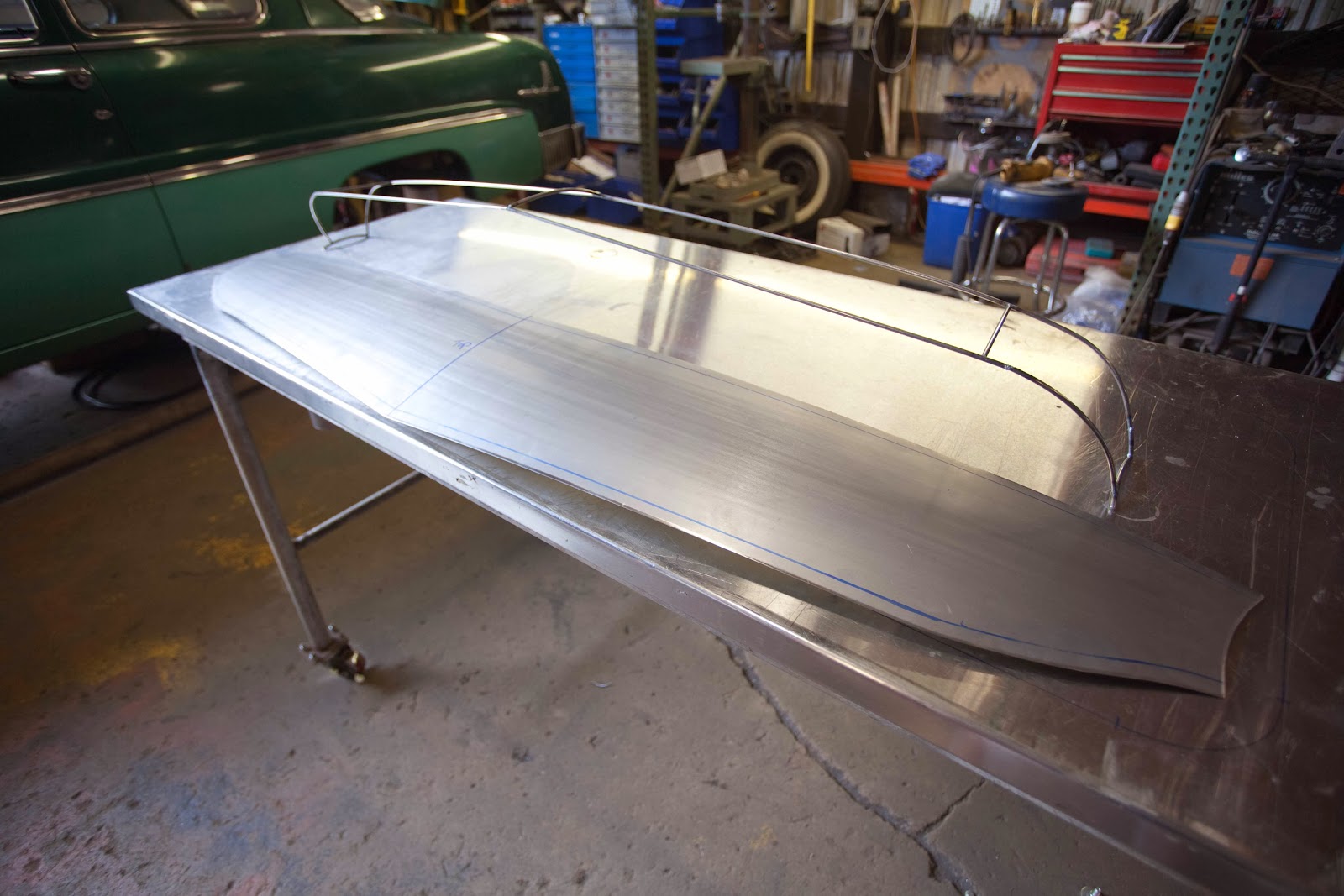
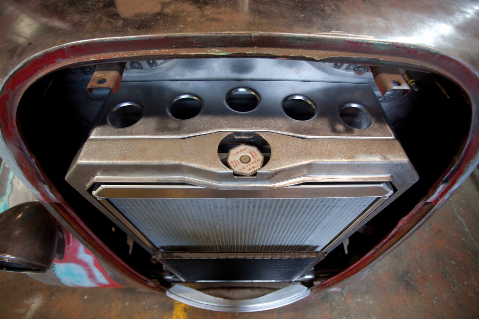
Chris started on the fan shroud for the radiator. We did not have a lot of room on the top part of radiator, because of the firewall. But it opens up at the bottom and gave us room for a 16" electric fan.


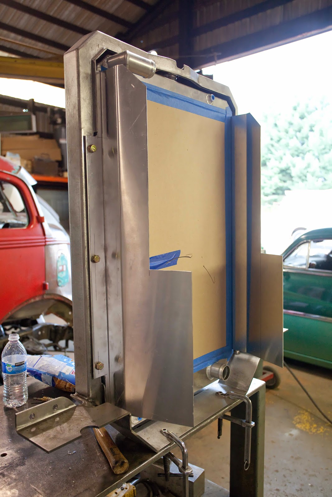
The sides go up first and then Chris built off that.


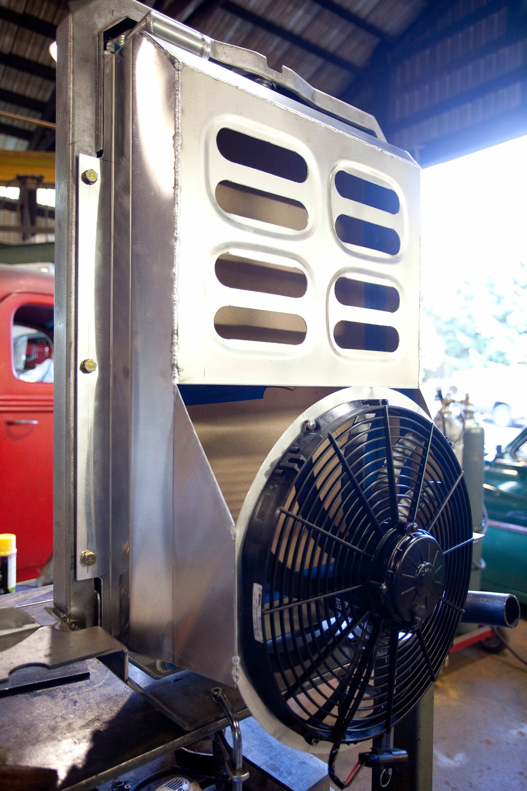
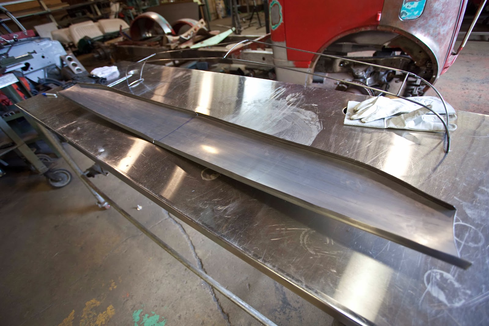
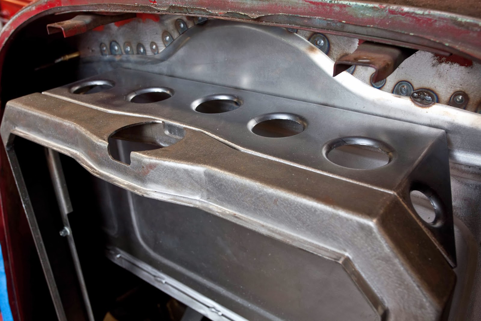
The top went on next then the back went on. We add vents in the top of the back for air to pass through when hitting cruising speeds. They will have rubber flaps that will sill the shroud when there is no air flow. Next Chris added the fan's mounting flange.


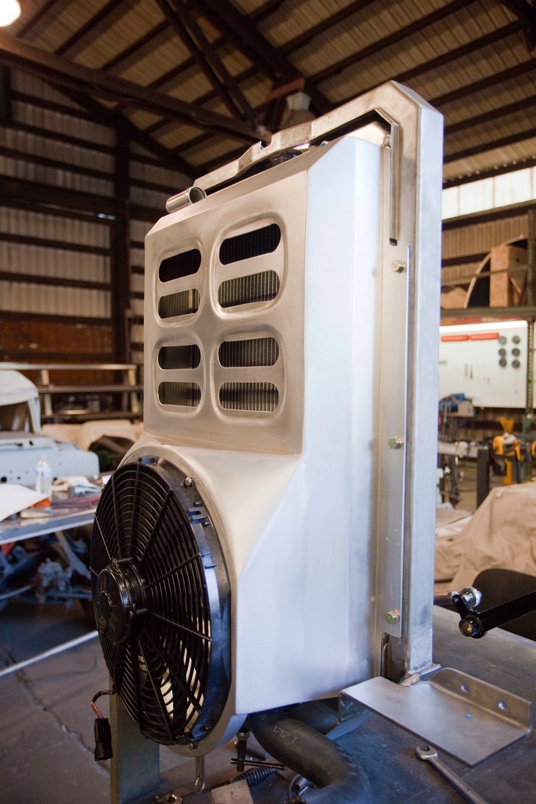
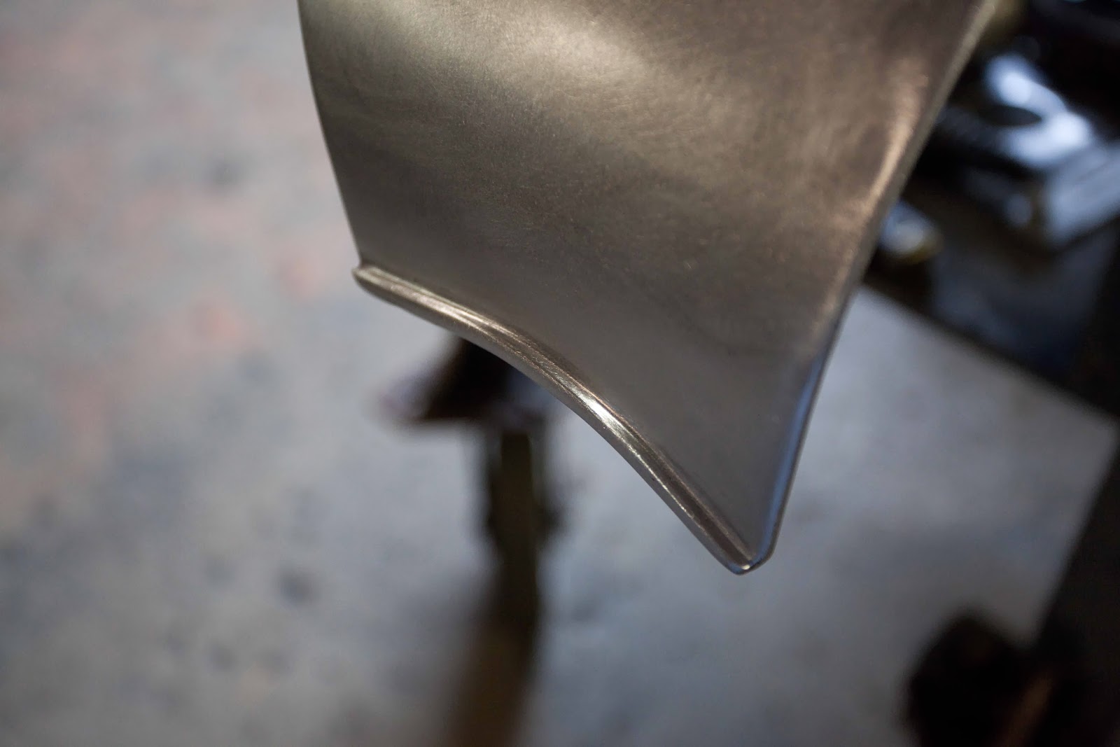
Last he filled in the rest of shroud, cleaned up the welds, and polished it up. We gave it a test with the battery charger and were very pleased on how much air was being pulled through the radiator. It even held a piece of paper on the air conditioner evaporator.


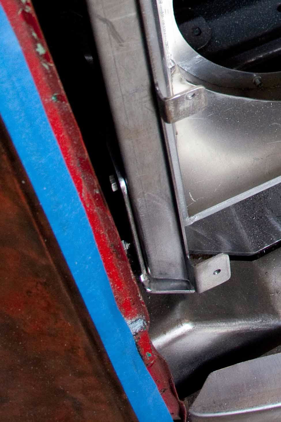
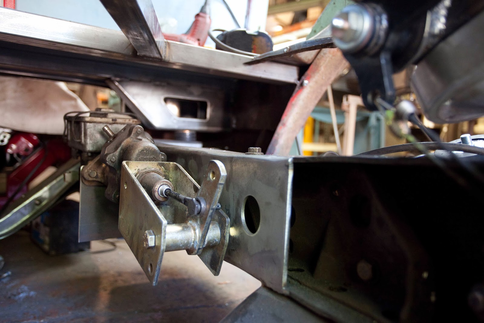
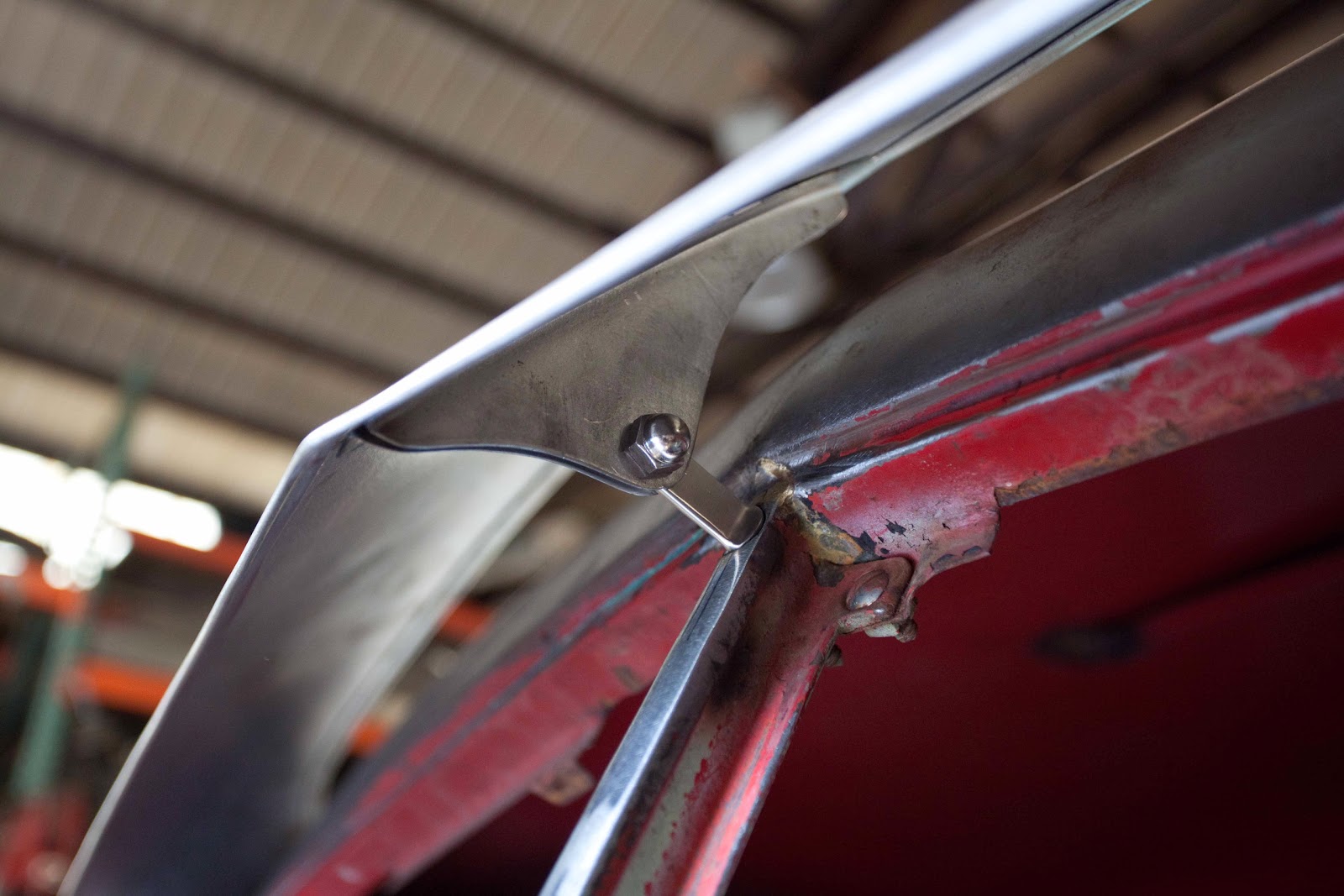
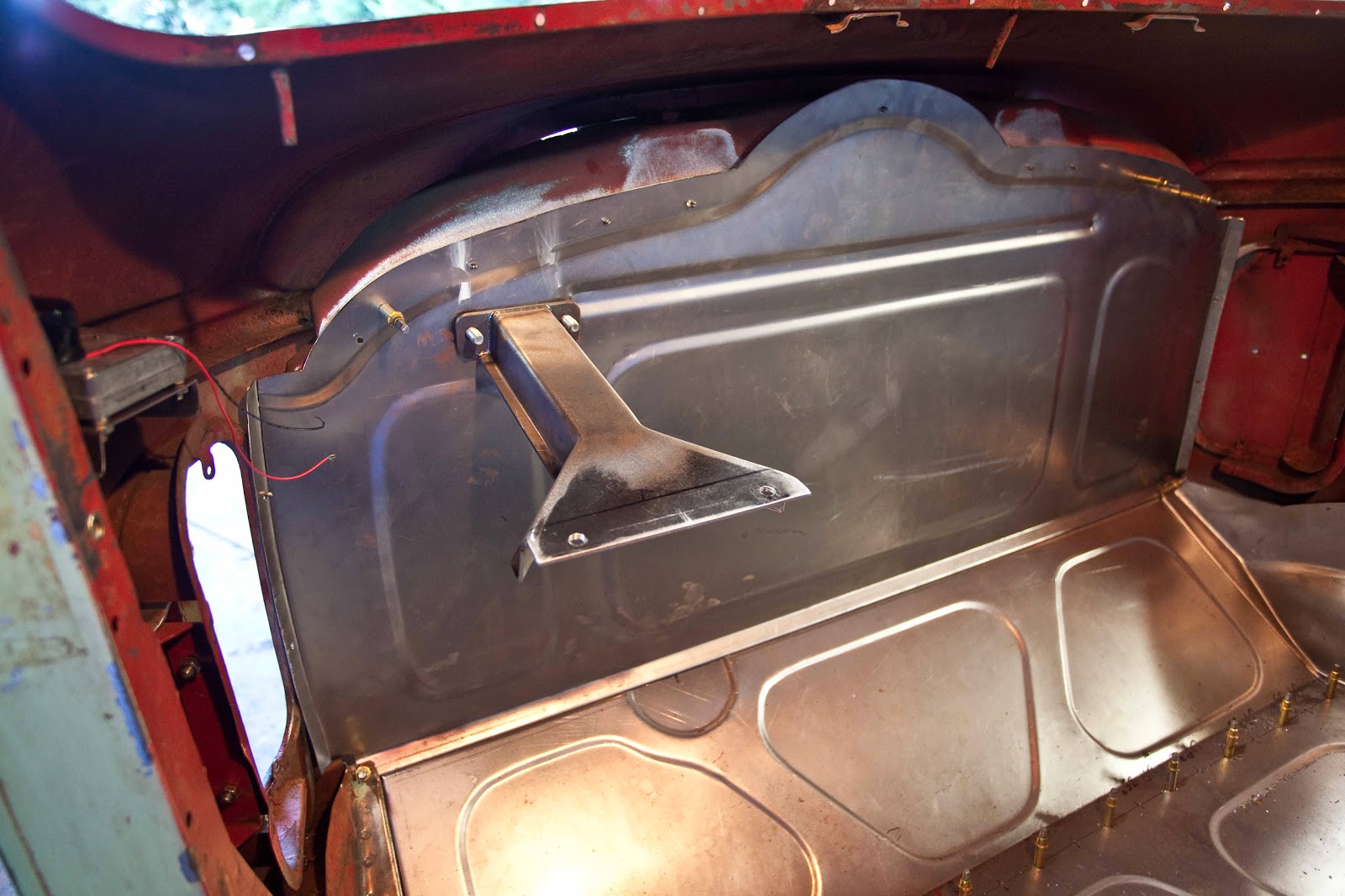
Chris made some adjustments on the radiator bracket to make it easier to install the fan shroud and radiator. 


The units will now be able to slide in and out from the front.


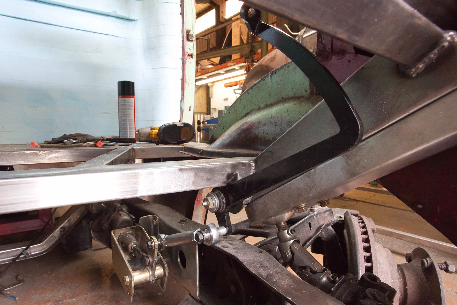
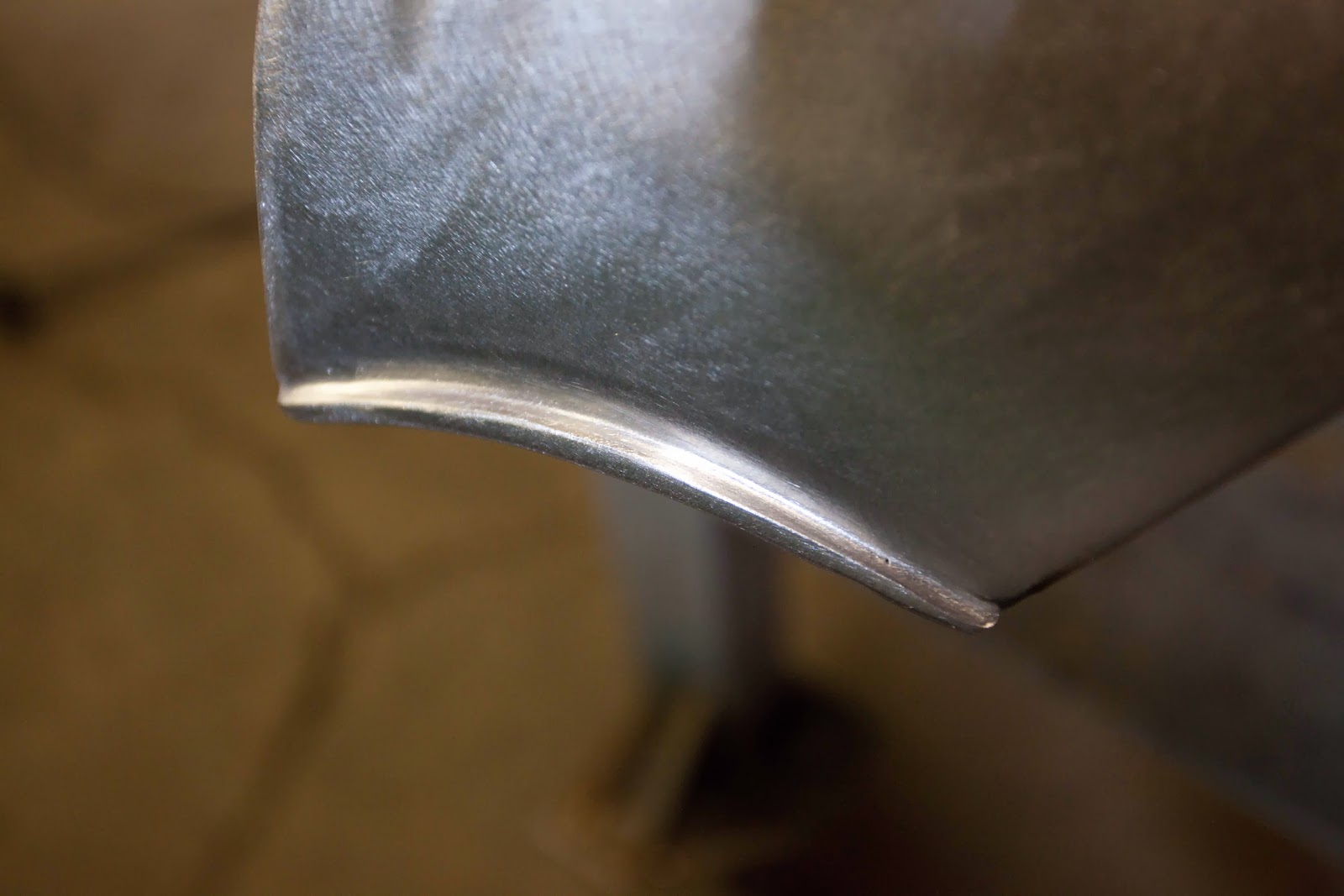
This will be the top brace for the radiator support.


The finish part installed.


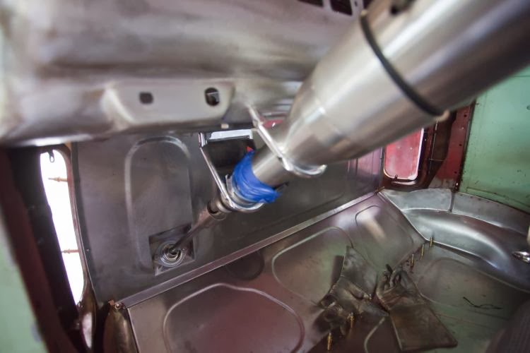
All together and ready to start running the lines.


More Work Inside the Cab

The new bracket for the steering is complete. Will also be running the brake pedal off the same bracket.


The bracket is welded between the two cross brace for a super strong hold.


Started to make a template for some interior parts for the cab. Will use the template for a fiberglass mold that will be covered with material that will match the seats.


Chris started on the brake pedal mounting. The pivot rod of the brake goes though the steering bracket and is welded 380 degrees and has its own bracket that is welded to the cross brace.


The master cylinder is mounted on the frame rail. The first mount is made and will be making one more. The mount still needs to be finished and beautified. Chris had a chance to finished up the brake setup today. I had taken the day off but will take pictures tomorrow of the finished setup and post them.


A better picture of the brake bracket. Needed to notch out the brace to make room for pedal travel.


The brake pedal all back together and notch is all fill in.


Both bracket finished and push rod installed.


Push rod is adjustable for different pedal heights.


Better look at the two brackets that hold the master cylinder.


Thank You Sam and Coolhand for your suggestions on making our brake setup more safe with the double shear. That is what I love about the H.A.M.B. you can get advice and knowledge from a bunch of great guy's and gal's. This is the setup we came up with.


Looking down from the driver seat.


Also did the lower bolt to. Still need to work on the length of the bolt.

Custom Visors - Of Course

Starting to layout the custom sun visor. Used 3/8" rod to form up the structure.


Covered the structure with cardboard to make the template for the sheet metal.


Getting ready to cut out the metal. Added a 1/2" to the pattern for a hem seam.


After some work in the english wheel.


Tip the lip on both sides to form the hem seams. Tip past 90 degrees then hammered down to finish it up. Next Chris used a mechanical brake with a 2 1/2" dye to form the sides of the visor. Sorry I got caught up in the moment and forgot to take the pictures of some of the last steps. 


Need to made the mounting hardware and do some fine tuning and that should finish up the visor.


Chris built the new hardware that will attach the visor to the truck and finished dialing in the rest of the final fit. Here he drilled and tapped the center post to accept a screw that he made with a post so that it would connect to the hardware on the visor. 


These are the right and left side of the visor that fit inside the drip rail that are tapped on the bottom and then screwed in through the bottom of the drip rail.


After trying out two column drop brackets and two different kind of universal joints we were able to get the steering setup all worked out. We used a steer clear to help out on the setup. Next we will make the bracket that will hold the steer clear stationary.


Used a bearing through the fire wall to support the shaft that goes to the steer clear from the column.


This is the bracket that supports the dash and the column drops.


The two column drops that we used and we also used a universal vibration dampener joint instead of a rag joint.

Summer Update

Have some updates on the truck. It's been a busy summer with the family, but Chris has been working on it a little while we been off playing.


Chris finished up the new firewall and added some nice bead rolling detail.


Needed to move the steering column bracket on the dash to center it for the new column and new seat set up.


Ready to install and test fit the new column.


Column matched up great. Time to work on some brackets to support the column and dash to the firewall.


Had to pull off the steering part of the project due to some of the u-joints did not work out as planed. While waiting for parts we moved on to some other areas of the project.


We did away with the manual operation of the door vents. Had a good friend machine up some parts to make the setup work. Replaced the stock rivets that held the hinges together with brass bushings and a rod that goes to the motor. Welded one set of bushing to the door hinge with a set screw that is connected to the rod. The other hinge has a free bushing that allows the door to open and close.


The motor was a little off set from the rod so we used a heavy duty spring to get them to lined up. When we test out the door it had a little delay and didn't have a smooth opening motion. The spring did not work out as we thought it would and now plan on trying to use a u-joint instead. It still looked pretty cool just need a little more fine tuning.

We had some rust issues in the front cab seam that need some attention. Decide to go with the one piece smooth look.http://www.jalopyjournal.com/forum/picture.php?albumid=37247&pictureid=477179


Chris was glad to see this part done. Said it would have been easier to have chop it.


Started to work on the front suspension to accept the new air bag setup. These are the parts that we used to make it happen.


First we leveled out the stock shock cup with table with the height that we needed the new cup to be. It worked out that we needed it to be 1.5" deeper then the stock cup.


Made a jig to transfer the circumference that we needed to cut out of the a-arm. Looks a little archaic but worked out great.


Chris cutting out the a-arm. Have to have a action shot once in a while .


Not much left. It's okay it all works out in the end. The air bags max out is 9.1" went with a 10" circumference for the clearance.


The new cups made and ready to get welded in.


Here is part two of the front air bag upgrade. Used 1/2" rod on the sides of the 10" tubing to join it to the a-arm.


The finished product after welding, grinding, and some sanding. Had to add on a new bracket for the shock mount. Will also need to add a new bump stop and bracket for the sway bar.


Time to start on the upper cup that will hold the top part of the bag.


Needed to raise the bag out of the upper pocket for clearance issues. Used 6" tubing for this. Trim it down to sit flat over the stock rivets.


Top plate that will hold the bag. 


The pieces put together and ready for a test fit. Inside is 1/2" sleeves that bolts through the top of the main carriage. 


This is about the ride height that we think the truck will ride at. And yes the unit is pictured upside down.


This will be the truck at its lowest point. Looks like the new setup is going to work out as planned.