Saturday, March 5, 2016

Side View Cameras and More Box Panels


Well we had to do some going backwards on how we planned on doing the side cameras. We thought that we would make a continuation of the running boards to house the cameras, but the part look like we just thru a box on the side of the panel. It was big and took away the curvature of the box. This left us with a gap between the running board and the box that we need to fix.  

Here is the gap that we want to close up.

 It was painful to take the paint off the finished running board. 

 Added in about a inch and a half and tweak the outside edge to match the box.

 Now all we need is some paint. 

 How we needed to come up with a new plan to house the cameras. We came up with making some blisters like you see on some 32 fords and aircraft. So we took some of the stuff that we learned from a workshop that we took from Ron Corvell. 

 To start we made positive mold out of some clay that was bake to make it hard. Didn't get pictures of it before it got destroy when making the negative part of the mold which you see here in this picture. Next we took MDF and used a router to cut out the shape. Went down a little deeper then the positive mold depth but kept the exact outside shape of the mold.  Next we drill holes in the bottom of the mold so that when we filled up the mold with body filler and press the positive mold in the excess material had a place to go. We used packing tape on the positive mold so it would not stick to the bondo, it work pretty well but had to come out in a few piece. When done you have a negative mold for hammer forming that's pictured above. The MDF in the background is made to the same shape as the part to hold the metal in place when forming the part.

 The metal would be sandwich between the mold and the top MDF part. Then you just start hammering away.

 This is what the part looks like after your done hammering. Okay maybe we had to do some filing and sanding to get to this point.

 When your done you have two parts the same. 

 Mounted and cut out the hole for the camera in the box.

 Its mounted low on the box. The camera has a very wide angle of view and can pick up at least two lines of traffic.
  
 The blister in place with the hole cut out for the camera.

 Getting ready for the weld.

 All welded in

 We are really happy how this turn out and it looks way better then the first choice.

Even though we lost two days on the first parts it was worth it in the end.

Back on body lines. We spent some time on test panels to make sure that we had our technique down before starting on the ones that count. Finished up the final layouts on the panels before getting started.
  
 Making sure that all the lines are matching up.

 The outside body line has to be right on because it is also the back gauge for the die.

Double checking out everything before we get start.

 We use a backstop for the double body line.

This was the die setup for the outer body line. We add a backstop to the top and extended piece to the bottom to help keep the material 90 degrees to the dies.
  
The finish piece after we ran both body lines. No pictures of the process haven't figure out how to hold a camera and help out Chris with the panels. We even enlist Chris's wife to help out with the panels.   

 We did have some shrinking and movement in the panels causing some oil can spots. So some hammer and dollie work will need to be done. In the end we have a usable part and the body lines match up well.

 The back gauge and body line done.

 Getting ready to run the outer body line.

 We were able to get a real nice line with the help of the backstop and Chris steady hands.

 Just finished up the outer body line.

 A profile look at the body lines.


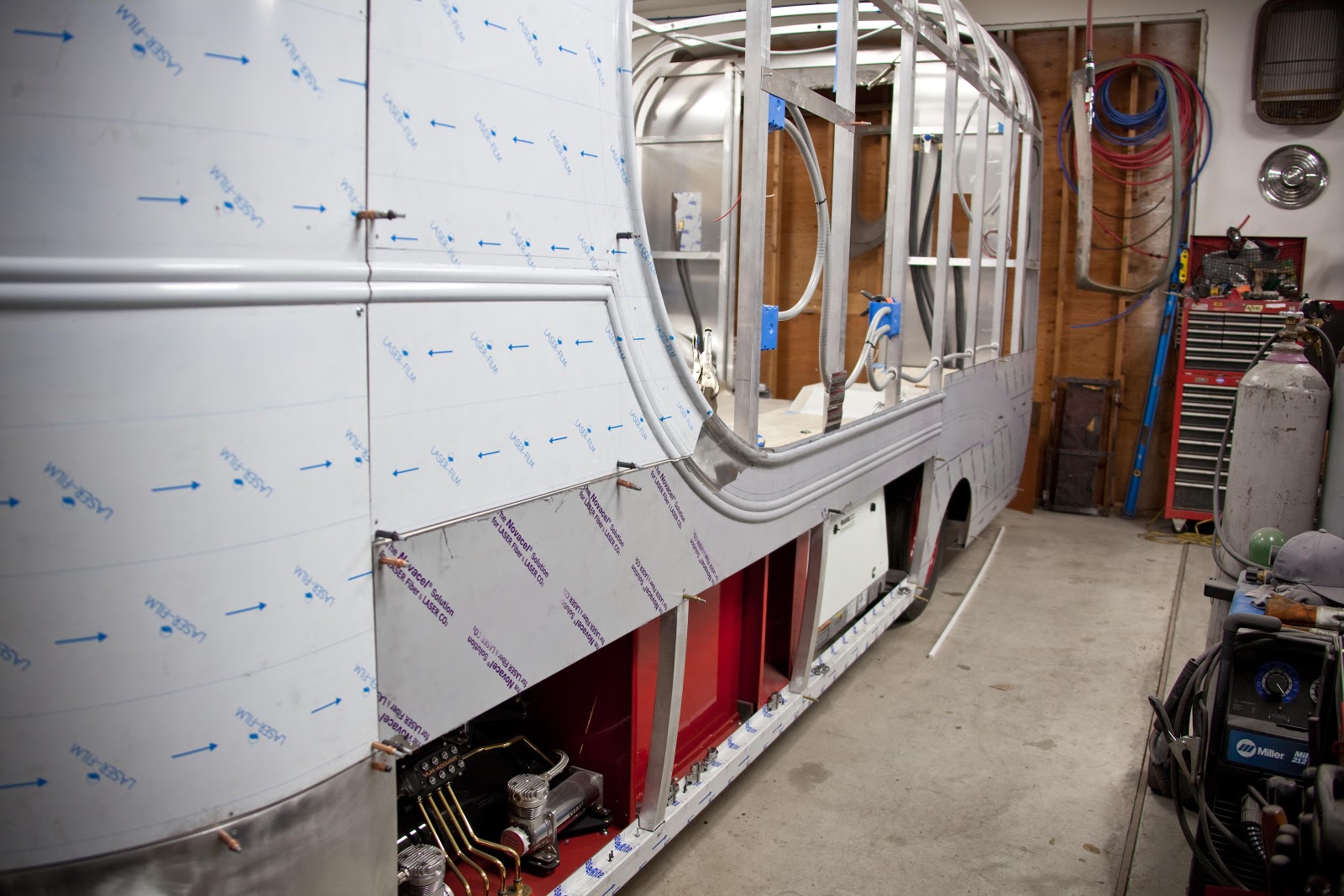
The parts on the truck for test fitting. Real happy on how the body lines are matching up on the all the panels. Laying out the last side panel for the truck and then the top panels for the roof and then we should be done with the body lines.

Thursday, February 4, 2016

Box Corners

Bottom flange for the lower corners of the box with the channel add in for the led lights.

We have a die for the pullmax that forms half of the radius in the part. 

Here is the part with the other half of the radius formed in

The two parts tac welded together to form the complete radius.

Chris will finish out the rest of the welding and finish work after we have test fitted the parts to the body.

 The lower corner in place.


We had the simple radius's for the corners rolled by Kyro Rolling.

Both sides done and ready to put in some body lines.

To get the layout of the body line we made a backstop so that the dies would follow the path that we wanted.

We have the backstop clecoed to the part and getting ready to start forming the body lines. Down below are pictures of the finish body lines in the corners. The Pullmax is a truly amazing  piece of equipment.


We placed the top corner on to see how it will look all together. Still need to do some more work on the top corner for a proper fit.


We are as far as we want to go on the front sheet metal till we remove the cab. We still need the cab on for the placement of the exhaust pipes. Then it can be removed to finish up the rest of the front sheet metal. 

Next we will be making a lower piece that will run along the bottom part of the lower  box corner that will house the side video cameras.
  
The cardboard templates for the lower camera housing. The chrome housing on the table is the stock housing that the camera came in and the one we model are part from.

Saturday, January 9, 2016

We Have A Cab

 Paul and Chris doing some rough final adjustments to the trim piece before the final shaping. Paul helped us out on doing some nice mill work to get us close to the shape that we were looking for. Chris then hand sanded to the final shape.

 Some blocks Paul made to hold the parts for when he milled them.

 The top square stock is what we started out with and bottom is almost the finished piece.

 We inserted a Ford hood emblem into the trim piece. All hand filed to fit into the trim.

 All finished up and ready to be shipped off to be chromed.

 The cabs back to the shop and is ready to be fitted to frame. The cab will go on the frame to match up the body lines that will be put into the box. Then it will come off again to do the bodywork and paint on the truck box.

 We made special brackets and used a gantry crane to assist us on putting the cab on the frame.

 We made it onto the frame but decided that we will use one more body to help next time. I will say it was a little stressful.

 Side view with lower apron and running broad to see how we did on matching up the box to the cab. The only thing we would change is that we ended up with about 1" between the cab and box and it would be nice to have another 1.5".
  
 We are very happy how the portion are working out between the cab and box.

 Starting to work on making a buck for the front box corners.

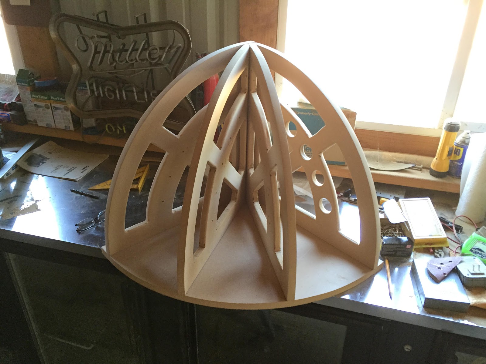
 Used 1/2" MDF to make the buck and had to make it look cool so we added some windows to it. The windows also help to see how your metal is fitting to your buck.
We used a 20" radius for the corners of the cab.

 The finished buck.

 Making a paper pattern off the buck for the sheet metal that will be formed.

The folds in the paper give us a guide on where to do the shrinking on the panel.

 The paper in the flat. This is what we will use as our template to cut the aluminum.
  
 We are using .080 aluminum for all the exterior panels. We also laid out all our shrinking lines on the aluminum from the pattern.

 The Pullmax at work with the shrinking dies.

Chris hard at work on the panel.

 Not much to look at and you wonder if it will ever be a usable part.

Next up is the English Wheel that will smooth and do the final shaping.


Here is the new English Wheel that Chris just finish up. Its time now for him to do his magic.

 I got so caught up in watching Chris on the English Wheel I forgot to take pictures of how we got to this point. Well it was a lot of wheeling and shrinking the outer edge and fitting to buck to get it to this point. It is real close but needs to be cleaned up some more.


We stop at this point but will do some more adjustment to the panel after we fit the side and top panels. We made the bottom pattern and will work on that next.

 Here is the bottom panel with the rough 20" radius on top and 18.5 radius on the bottom. The panel also will have a slight contour shape that we will achieve with the English wheel.
  
 We use a slip roller to get the radius in the part.

You can see the contour that was put in the panel. We layout lines on the panel to help with  the tracking of the English wheel. This really helps out when your just starting out on using a English wheel. You can make a really bumpy panel fast without a good tracking pattern. 


We been working on some other aspects of the project so that we can continue to move forward. Took measurement and cut material for the other 20" radius's that we need to complete the box. These will be all simple 20" radius's that we are having rolled. Also been tuning in the dies and practicing on our skills for the body lines. Once we have the the body lines master we can finish up the panels that go to cargo doors and then get the final measurement for the doors. Lots more in the works will keep you posted and Thanks for watching.